34+ transfer function to block diagram
The transfer function for the system a A car is towing a small camper trailer behind it on. Enter the email address you signed up with and well email you a reset link.
2
Show transcribed image text.
. Use MATLAB and the block diagram to define the transfer function and then plot the Bode plot. Hence b c This system has the same transfer function determined in part a because multiplication of. A block diagram for the system 2.
Also the transfer function of a single block is its output-to-input transform. For the closed-loop feedback control system with input Rand output. If you are looking for Intro to Control 102 Closed-Loop Transfer Function YouTube youve visit to the right place.
Transfer Functions and Block Diagrams 21 Introduction - Review of Laplace transform - Using Laplace transform to solve a differential equation 22 Review of Laplace Transforms. A block diagram can be used simply to represent the composition and interconnection of a system. The most common technique used for modeling linear time-invariant systems is the block diagram with the mathematical model represented as a transfer function.
ME2142 Feedback Control Systems Worked Examples on block diagramstransfer functions 31stJanuary 2012 1. Also it can be used together with transfer functions to. 2 Y s X s H s So the purpose of the.
Transfer functions and their corresponding block diagrams are shown as a reference for how to manipulate or construct one from the other. Transfer Function and Block Diagram Continued Consider a closed-loop transfer function Hs b 0sm b 1sm1 b m1sb m a 0sn a 1sn1 a n1sa n Bs As. It is usually the case that you are given the input X s and the transfer function H s and so equation 1 is re-arranged as.
You have a feedback loop inside the block diagram so you need to introduce another state variable qn which in this case is the signal right after the first. It consists of unidirectional operational blocks that. How to draw block diagram from given transfer function in state space analysisTransfer function to block diagram conversionFull Series-Semiconductor Device.
We have 9 Pics about Intro to Control 102 Closed. Block diagram models The block diagram is a diagrammatic means to represent the cause-and-effect relationship of system variables. This problem has been solved.
The sensor transfer function is a gain and the controller which has no derivative contribution is a PI. Figure 556 Block diagrams and transfer functions and rearrangement gives. Transfer Function Block Diagram.
Your friend is correct. A simple system of equations for the problem 3.
1
Introduction To Electrical Engineering Notes 48510 Introduction To Electrical And Electronic Engineering Uts Thinkswap

Reduce The Block Diagram To A Single Transfer Func Transfer Function Block Diagram Diagram
1
Automatic Link Establishment System

Block Diagram Of Closed Loop Control System System Control System Transfer Function

Dynamic Behavior Of Closed Loop Control Systems Control System Laplace Transform Transfer Function

Control System And Types Of Control System Electrical Paathshala Control System System Transfer Function
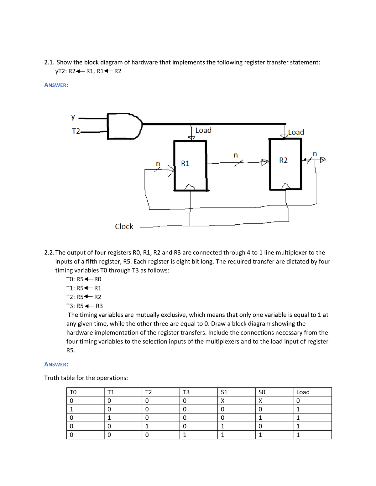
4 6015049101878495567 Copy Show The Block Diagram Of Hardware That Implements The Following Studocu
1

Block Diagram For Open Loop Control System Control System System Control
1

Resource Html Uri Celex 01985r3821 20160222 Eng Xhtml L 2002207en 01015801 Tif Jpg
Automatic Link Establishment System

Block Diagram Reduction Problem Solving Block Diagram Flow Chart

Ultra High Resolution Linear Ion Trap Orbitrap Mass Spectrometer Orbitrap Elite Facilitates Top Down Lc Ms Ms And Versatile Peptide Fragmentation Modes Molecular Cellular Proteomics

Canonical Form For Closed Loop Systems Control System System Control